How the VortexWell works
Fluid flowing around a blunt object in its path, such as a standard thermowell, forms vortices downstream of the object – commonly known as vibration induced vortices and the implications this can have are huge, from in-accurate readings to complete failure of the thermowell.
As the vortex shedding frequency approaches the thermowell natural frequency, the tip displacement and stresses are greatly magnified and the thermowell can fail. Even when the thermowell has passed calculations to the ASME PTC 19.3 standard, failures are still known to have happened, Monju Power Plant being a prime example.
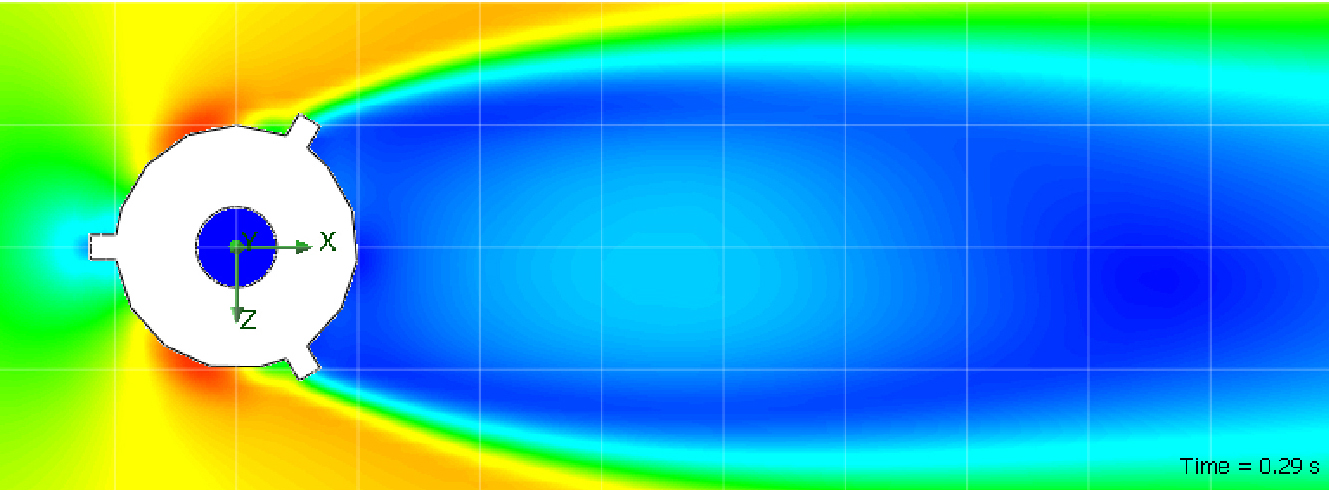
Look at the image below. This was taken from an independent CFD report undertaken by Cygnet Development Services Ltd. This shows the velocity plot of the flowrates around a standard thermowell with the formation and shedding of vorticies clearly identifiable.
.jpg)
To solve this issue, we looked at several different ideas, from increasing damping to streamlined cross sections. It was found that the best solution was to incorporate a helical strake as a vortex suppression method which made our VortexWell the best performing and safest thermowell available.
From the same report by Cygnet Development Systems, the image below shows the velocity plot of the flowrates around an Okazaki VortexWell Thermowell which clearly demonstrates that this design greatly reduces vortex induction. In fact, results have shown that the VortexWell eliminates over 90% of dynamic stresses.
